Internal speaker
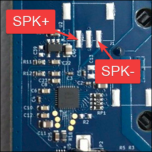
Both versions have a similar layout for the pins you need to use. In the H1, the connector might not be populated and look like this:
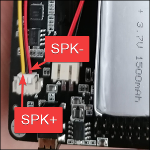
On the H2, normally the connector and cable (use the red and yellow wires, isolate the black one) is included as seen here:
For both versions, you need a small speaker. Typically a laptop speaker will work, for example: https://a.aliexpress.com/_mLuZk4U
Connect SPK+ and SPK- to the speaker and use double sided tape to fix it to the PCB.
Speaker test: https://www.youtube.com/watch?v=XkaGV9muvbg
A speaker has two wires, SPK+ and SPK-. While there is no sound, the speaker floats on a magnetic field in the middle of its range. When SPK+ is high the speaker moves forward. When SPK- is high the speaker moves backwards. The distance forward and backwards depends entirely on the voltage level.
On the PortaPack, the speaker connector has 3 pins.
SPK+ is the pin nearest to the edge of the board
GND is the connector in the middle, skip it
SPK- is towards the centre of the board
On the H1 with an AK4951 codec, when you add the new speaker you may find that there is no audio. In this case, use the speaker icon on the title bar to enable the speaker output (grey with "X" indicates muted; green with no "X" indicates it's unmuted).
Warning: Do not set the speaker icon to "unmuted" if the speaker already works when "muted", as on one model of the OpenSourceSDRLab PortaPack H2 which has two audio chips with their outputs tied together (overheating will result if they're both enabled).