gQuintic Specs
-
Runs g2core codebase
-
Processor
- Atmel SAMS70N19A ARM Cortex M7 processor
- 300MHz internal clock
- 32 and 64 bit single instruction floating point hardware
- Multi-level cache, instruction pipeline, simultaneous instruction execution
- All communications IO is DMA driven
- We have seen 10x to 80x performance improvements relative to 84Mhz M3 core
-
Host and Communications
- USB-B connector for driving from "standard" external hosts
- USB is on-chip w/custom USB drivers - field tested for about 2 years now
- Supports 480 Mbps transfer rates
- Host expansion connector for Linux host carrier board
- Board design accommodates Linux daughterboards, hosting Beaglebone, rPi variants, etc.
- USB-B connector for driving from "standard" external hosts
-
Motors
- 5 motor outputs - may be a mix of:
- 5 Trinamic TMC2130 stepper motor drivers
- Will handle up to 1.7 amps;
- Good for almost all NEMA17 motors, will do some NEMA23s
- 5 STEP / DIRECTION / ENABLE breakouts for external drivers
- selectable 3.3v/5v output levels
- 5 Trinamic TMC2130 stepper motor drivers
- 4 "hobby servo" PWM outputs (uses the buffered digital outputs)
- can be configured to interpret Gcode directly, or run as PWM devices
- 5 motor outputs - may be a mix of:
-
Digital Inputs
- 10 digital inputs
- ESD protected & RC deglitched
- light pullup to 3.3v
- 3.3v and ground available on each connector
- 10 digital inputs
-
Analog Inputs
- 4 ADC inputs (analog to digital)
- configured as straight-through 0.0v - 3.3v ADC channels
- use external RTD front-end boards to run 100K thermistors, PT100, PT1000
- use external load cell front-end boards to terminate standard 1mv/V load cells
- OEM boards can be configured on-board for RTD termination
- 4 ADC inputs (analog to digital)
-
Digital Outputs
- 4 buffered digital outputs - jumper selectable for 3.3v/5v level
- 4 low-power FET digital outputs - up to 300 ma each (for fans, etc.)
- 3 high-power FET digital outputs
- 2 extruders @ 6A
- 1 heated bed @ 20A
- Neopixel LED array output with DMA firmware driver
- All digital output channels can be PWM driven
-
Analog Outputs
- 0-10 volt digital to analog converter for running variable frequency drive spindles
- uses one of the 4 low-power FETs channels for the VFD DAC
- 0-10 volt digital to analog converter for running variable frequency drive spindles
-
Voltages
- Supplied to board
- Vmot - Main motor and FETs (12v to 30vdc). Powers Trinamic TMS2130, High power Extruder FETs, Low power FETs
- Vmot2 - Regulator input (12v to 30vdc). Powers switching regulator.
- Typically connected to Vmot via on-board 0 ohm resistor, but may be powered independently of Vmot via J2 (0.100 2 pin connector)
- Vbed - Heated bed voltage (12v to 30vdc). Separate power input for heated bed
- On-board voltages
- +5v external - up to 1.5A available for any combination of:
- 5v power to daughterboard microhost computer
- 5v selectable for external stepper drivers
- 5v selectable for digital outputs - may be used to power hobby-servos directly or just provide PWM w/external power
- 5v for neopixel output
- +3.3v external - up to 100ma available for any combination of:
- Digital inputs
- Digital outputs (selecteable to 3.3v or 5v)
- 3.3v selectable for external stepper drivers
- +5v external - up to 1.5A available for any combination of:
- Supplied to board
-
Other
- Configured for daughterboard to carry Linux host computer (see Features)
- Watchdog safety circuit to disable powered outputs (see Features)
- Support for external ESTOP (see Features)
- SPI and I2C expansion port
- JTAG/SWD connection and real-time debugging using Atmel-ICE or other ICE
- ROHS
The gQuintic is designed to carry a daughterboard with a small host computer (presumably Linux). One connection to the daughterboard provides 5 volts at up to 1500 ma.
The Host Connector provides the following:
- 4-wire UART RX/TX/RTS/CTS. Supports Host-Board communication w/std Linux kernels
- Safety signals from board - de-assert if board is not functioning properly
- RESET and ERASE lines drivable from host
- Host interrupt line driven from controller MCU to notify the host of significant events
- Logic 3.3v and ground. 3.3v can be used to detect if logic power is present
The daughterboard may also bridge the SPI/ I2C expansion connector providing I2C and 2 SPI channels
Most product safety certifications (e.g. CE for Europe) for things like machine tools require that a redundant hardware failsafe be provided to shut down the machine in various failure cases. This should be in hardware, unless you have a software solution that is separate from the main SW, and the failsafe SW itself then needs to be certified (which we want to avoid).
gQuintic has a discrete multivibrator circuit made of two cockroach FETs (BSS84, BSS138) that asserts as long as a pulse train is present on the input. If the pulse train is not present or fails the safety circuit de-asserts. All the output FETs, the Step signals and the DAC voltage are gated by this SafeOut signal. The pulse train generator is in the main loop of the MCU.
Here are conditions where SafeOut would de-assert from hardware:
- The MCU is booting - and has not started the main loop yet
- The MCU is being flashed (and therefore not executing)
- Motor power is applied but for some reason logic power has failed or not applied (the MCU is therefore not functioning)
In addition, there are software conditions that remove the pulse train and de-assert:
- The firmware is off in the weeds and the main loop has been terminated accordingly
- A failsafe assertion in the code has triggered, placing the firmware into a PANIC or ALARM state
- An external shutdown has been detected placing the system into a SHUTDOWN state (see Emergency Stop, below)
Background and philosophy: Since the controller may be the cause of a problem requiring an emergency stop, the controller should never be in the critical path of an emergency stop.
The gQuintic is designed so motor and FET power can be killed by an external switch independently while the processor continues to receive power and operate. The incoming Vmot (typically 24v) has two connectors - One high-current to power the motors and FETs, another low-current to feed the regulator stages. These can be bridged for single-connection configurations.
If Vmot drops a number of things happen:
- The motors, FETs and DAC de-power - this includes the high-current FETS (heaters), and the low-current FETs and the DAC output will drop to zero (The DAC is 0-10v, typically used for spindle speed)
- The Trinamic rail voltages drop in order to prevent them from blowing up (they may be damaged if you don't remove power)
- The CPU receives a LO on a pin, which can be used to signal the firmware that an external Estop has occurred (really that Vmot has been lost). The firmware enters a Shutdown sequence, where it stops motion, shuts off the Safety signal, and informs the host that this has occurred.
TODO: Place image of silk screen on page
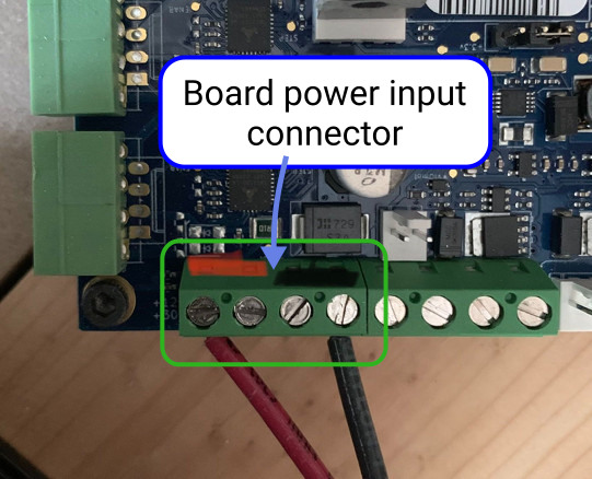
Board power input connector (12-24v)