PID control
PID control is very common in many applications. While conceptually simple it poses some challenges for simulation using bdsim.
The controller in transfer function form is
where
As written, this has has a feed through term, the output depends directly on the input if
The second (derivative) term also poses a challenge. The required transfer function
where the filter pole (bdsim because it also has direct feed through. We can see that by rewriting the transfer function
Alternatively we could rewrite the transfer function of the derivative term
as
which we can implement as a simple block diagram
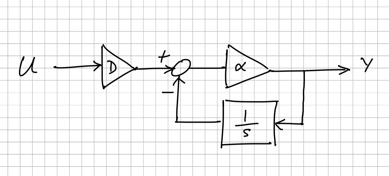
which is known as a complementary filter. This way we sidestep the issue of non-proper transfer functions. The DERIV block is a subsystem that implements this small block diagram.
We can implement the third (integral) term as an LTI SISO transfer function.
The requirement for "no feedthrough" is a consequence of the way bdsim integrates the system dynamics. Without this requirement we would have algebraic loops which would need iteration to resolve at every time step.
Since no bdsim transfer function block can have feed through, we have to express the PID controller as three blocks whose outputs are added by a summing junction, something like
pid_proportional = bd.GAIN()      # proportional block
pid_deriv = bd.DERIV()            # derivative block
pid_integrator = bd.INTEGRATOR()  # integrator block
pid_sum = bd.SUM("+++).           # sum of all three blocks

bd.connect(U, pid_proportional[0], pid_deriv[0], pid_integrator[0])
bd.connect(pid_proportional[0], pid_sum[0])
bd.connect(pid_deriv[0], pid_sum[1])
bd.connect(pid_integrator[0], pid_sum[2])
noting that the DERIV block is itself a subsystem.
The PID block implements this scheme and supports a number of options such as:
- a reduced controller that leaves out some blocks for the PI or PD cases
- an integral band, the integrator is only enabled when the error magnitude is below a threshold
- bounds on the integrator state
See examples/pid.py for an example that uses the PID block.