Part 1: crude 3D renderings
The project depends on SDL2, but the GUI and event handling appear quite late, (midnight Saturday :) We can do all the rendering without any GUI libraries.
So, I start with a bare C++ compiler, nothing else. I break the code into steps; as in my previous articles on graphics, I adhere to the rule "one step = one commit". Github offers a very nice way to highlight changes made with every commit.
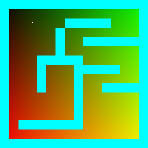
Okay, here we go. We're still a long way from the GUI, so first we'll just save pictures to disk. Altogether, we need to be able to store an image in the computer's memory and save it to disk in a standard format. I want to get a file like this one:
The full C++ code for this step is available in this commit, it is short, so let us list it here:
#include <iostream>
#include <fstream>
#include <vector>
#include <cstdint>
#include <cassert>

uint32_t pack_color(const uint8_t r, const uint8_t g, const uint8_t b, const uint8_t a=255) {
    return (a<<24) + (b<<16) + (g<<8) + r;
}

void unpack_color(const uint32_t &color, uint8_t &r, uint8_t &g, uint8_t &b, uint8_t &a) {
    r = (color >>  0) & 255;
    g = (color >>  8) & 255;
    b = (color >> 16) & 255;
    a = (color >> 24) & 255;
}

void drop_ppm_image(const std::string filename, const std::vector<uint32_t> &image, const size_t w, const size_t h) {
    assert(image.size() == w*h);
    std::ofstream ofs(filename, std::ios::binary);
    ofs << "P6\n" << w << " " << h << "\n255\n";
    for (size_t i = 0; i < h*w; ++i) {
        uint8_t r, g, b, a;
        unpack_color(image[i], r, g, b, a);
        ofs << static_cast<char>(r) << static_cast<char>(g) << static_cast<char>(b);
    }
    ofs.close();
}

int main() {
    const size_t win_w = 512; // image width
    const size_t win_h = 512; // image height
    std::vector<uint32_t> framebuffer(win_w*win_h, 255); // the image itself, initialized to red

    for (size_t j = 0; j<win_h; j++) { // fill the screen with color gradients
        for (size_t i = 0; i<win_w; i++) {
            uint8_t r = 255*j/float(win_h); // varies between 0 and 255 as j sweeps the vertical
            uint8_t g = 255*i/float(win_w); // varies between 0 and 255 as i sweeps the horizontal
            uint8_t b = 0;
            framebuffer[i+j*win_w] = pack_color(r, g, b);
        }
    }

    drop_ppm_image("./out.ppm", framebuffer, win_w, win_h);

    return 0;
}
If you don't have a compiler on your computer, it's not a problem. If you have a guithub account, you can view, edit and run the code (sic!) in one click in your browser.

When you open this link, gitpod creates a virtual machine for you, launches VS Code, and opens a terminal on the remote machine. In the command history (click on the console and press the up key) there is a complete set of commands that allows you to compile the code, launch it and open the resulting image.
Warning: my code is full of bugs, I fix them in the upstream, but older commits are affected. Check this issue.
So, what do you need to understand in this code? First, I store colors in a four-byte integer type uint32_t. Each byte represents a component R, G, B or A. The pack_color() and unpack_color() functions allow you to work with color channels.
Next, I store a two-dimensional picture in a normal one-dimensional array. To acces a pixel with coordinates (x,y) I don't write image[x][y], but I write image[x + y*width]. If this way of packing two-dimensional information into a one-dimensional array is new for you, you need to take a pencil right now to make this perfectly clear, because the project is full of such things. For me personally, this calculation does not even reach the brain, it is processed directly in the spinal cord.
Finally a dooble loop sweeps the picture and fills it with a color gradient. The image is dropped to the disk in .ppm file format.
We need a map of our world. At this step I just want to define the data structure and draw a map on the screen. That's how should look like:

You can see the modifications here. It is very simple: I have hardcoded the map into a one-dimensional array, defined a draw_rectangle function, and have drawn every non-empty cell of the map.
I remind you that this button will let you run the code right at this step:
What do we need to be able to draw a player on a map? GPS coordinates suffice :)

We add two variables x and y, and then draw the player in the map:
You can see the modifications here. I won't remind you about gitpod :)
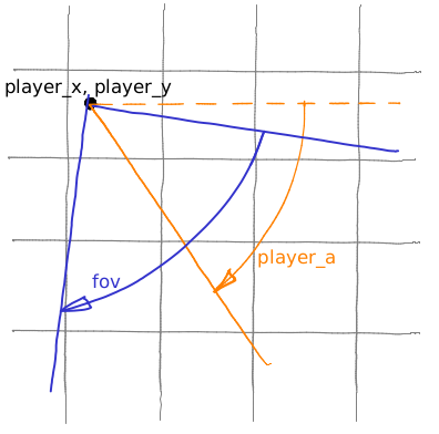
In addition to the player's coordinates, it would be nice to know in which direction he is looking. So let's add player_a variable, it gives the direction of the player's gaze (the angle between the view direction and the x axis):
Now I want a point to slide along the orange ray. How to do it? Look at the green triangle. We know that cos(player_a) = a/c, and sin(player_a) = b/c.

Now let us take an arbitrary (positive) value c and then compute x = player_x + c*cos(player_a) and y = player_y + c*sin(player_a). Obviously, it will give us the magenta point; if we vary the parameter c from 0 to +infinity, the magenta point would slide along the orange ray. Moreover, c is the distance from the point (x,y) to the point (player_x, player_y)!
The heart of our 3D engine is this loop:
   float c = 0;
    for (; c<20; c+=.05) {
        float x = player_x + c*cos(player_a);
        float y = player_y + c*sin(player_a);
        if (map[int(x)+int(y)*map_w]!=' ') break;
   }
We make the point (x,y) slide along the ray, if it hits an obstacle, we break the loop, and the variable c gives us the distance to the obstacle! Exactly like a laser rangefinder.

You can see the modifications here.
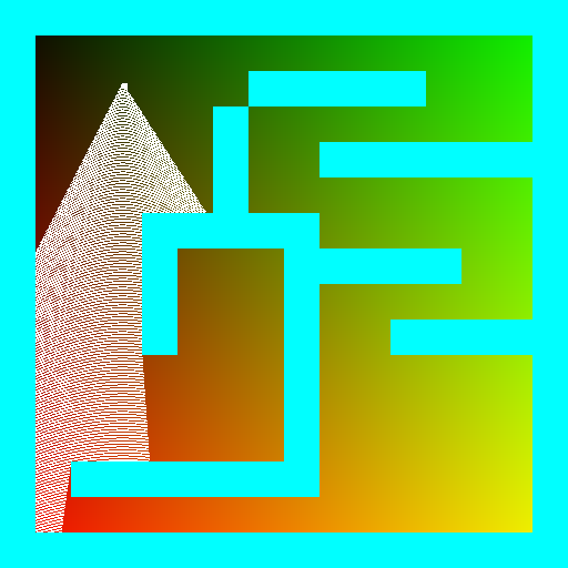
Casting one ray is good, but our eyes see a sector. Let us call the camera angle fov (field of view):
And then we cast 512 rays (by the way, why 512?), sweeping all the field of view:
You can see the modifications here.
This step is a key for the success. For each of the 512 rays we compute the distance to the nearest obstacle? Now let's create a second picture (spoiler alert!) 512 pixels wide. To make this picture we will draw vertical segments, one per ray we cast. The height of vertical segments is inversely proportional to the distance to the nearest obstacle:

Again, this is a key moment to create 3D illusions. Be sure you know what I talk about. When we draw vertical segments, in fact, we draw a palisade; the height of each stake depends on the distance from the camera:

You can see the modifications here.
At this step we first create something dynamic (I simply drop 360 pictures). It is trivial: in a loop I change player_a, render the image, drop it, change player_a, render the image, drop it. To better see what is happening, I assign a random color to each map cell type:
 You can see the modifications here.
Have you noticed nice fisheye effect in the above animation? If we look straight at a wall, we see something like this:

Why? Very simple. Let us suppose we are looking at a wall:

To render the scene, the magenta ray sweeps the field of view. Let us fix an arbitrary ray direction. The length of the orange segment is inferior to the length of the magenta segment. Each "stake" height depends on the distance from the camera (we divide the screen height by the distance to the "stake"), so the fisheye distortion is only normal.
It is very easy to correct this distirtion, you can check how it is made. Please make sure you understand where the cosine came from. Drawing a diagram on a piece of paper helps a lot.
