In this project, my goal is to write a software pipeline to identify the lane boundaries in a video from a front-facing camera on a car. The camera calibration images, test road images, and project videos are presented as output from the pipeline.
Introduction video :
The goals / steps of this project are the following:
- Compute the camera calibration matrix and distortion coefficients given a set of chessboard images.
- Apply a distortion correction to raw images.
- Use color transforms, gradients, etc., to create a thresholded binary image.
- Apply a perspective transform to rectify binary image ("birds-eye view").
- Detect lane pixels and fit to find the lane boundary.
- Determine the curvature of the lane and vehicle position with respect to center.
- Warp the detected lane boundaries back onto the original image.
- Output visual display of the lane boundaries and numerical estimation of lane curvature and vehicle position.
Brief description how the camera matrix and distortion coefficients are computed.
The code for this step is contained in the in the following method: utils.cal_undistort (line:5 - line:10 utils.py).
The input image is with the following dimension (1280, 720, 3)
The number of corners by x and y are assumed to be (9, 6)
I start by preparing "object points", which will be the (x, y, z) coordinates of the chessboard corners in the world.
The code that computes object points and image points is contained in the following method : utils.get_img_obj_points (from line:13 - line:32 utils.py).
Here I assumed the chessboard is fixed on the (x, y) plane at z=0, such that the object points are the same for each calibration image.
Thus, objp is just a replicated array of coordinates, and objpoints will be appended with a copy of it every time I successfully detect all chessboard corners in a test image. imgpoints will be appended with the (x, y) pixel position of each of the corners in the image plane with each successful chessboard detection.
Then, I used the output objpoints and imgpoints to compute the camera calibration and distortion coefficients using the cv2.calibrateCamera() function. I applied this distortion correction to the test image using the cv2.undistort() function and obtained this result:
Distortion correction that was calculated via camera calibration has been correctly applied to each image. An example of a distortion corrected image is included below

Description about how I used color transforms, gradients or other methods to create a thresholded binary image.
I used list of following thresholds
- Absolute sobel threshold (x, y) direction => Source:
utils.py#sobel_filter - RGB threshold on red and green colors => source
utils.py#rgb_filter - YUV threshold on s-channel => source
utils.py#yuv_filter - HSV threshold on s-channel => source
utils.py#hsv_filter - HLS threshold on s-channel and l-channel => source
utils.py#hls_filter
Below, the image describes how I combine all these thresholds for creating a thresholded binary image

Describtion about how a perspective transform is performed on image with included example
The code for my perspective transform is located in function perspective_transform
Inside this function, there is a function called warp_perspective, which appears in lines 224, ref : utils.py#perspective_transform The warper function takes as inputs an image (img), as well as source (src) and destination (dst) points. I chose the hardcode for source points and destination points are depended on the image dimension.
def get_source_points():
    return [[220,720], [1100, 720], [780, 470], [600, 470]]

def get_destination_points(width, height, fac=0.3):
    fac = 0.3
    p1 = [fac * width, height]
    p2 = [width - fac * width, height]
    p3 = [width - fac * width, 0]
    p4 = [fac * width, 0]
    destination_points = [p1,p2,p3,p4]
    return destination_points
This resulted in the following source and destination points:
| Source | Destination |
|---|---|
| 220, 720 | 384, 720 |
| 1100, 720 | 896, 720 |
| 780, 470 | 896, 0 |
| 600, 470 | 384, 0 |
I verified that my perspective transform was working as expected by drawing the source and destination points onto a test image and its warped counterpart to verify that the lines appear parallel in the warped image.

Once I applied calibration, thresholding, and a perspective transform to a road image, we have output binary output image with lines stand out clearly, as you can see on the picture above.
-
If it's the very first frame:
-
Create white color hitogram - Source: (utils.py#get_lane_rectangles line:234 - line:236)
Note : We should not start from lane line close to the center, exclude these points from the histogram -
Generate 2 base window points on left and right side where histogram shows highest concentration of white colors Source : (utils.py#get_lane_rectangles line:244 - line:245)
-
Foreach window - Source: (utils.py#get_lane_rectangles line:272 - line:307)
- Store all the points contained inside the previous calculated windows and compute mean X-position for both windows
- Generate 2 windows аbove the previous 2 rectangles, with the computed mean X-position respectively.
-
Generate polynomial based on the stored points from left rectangles and stored points from right rectangles - Source : (utils.py#get_lane_rectangles line:326 - line:334)
-
-
For all other frames : - Source: (utils.py#get_next_frame_lines line:346 - line:326)
- Get the right and left polynomials that are calculated in the previous frame
- Store all points contained near defined offset from polynomial lines - Source : (utils.py#get_next_frame_lines line:360 - line:369)
- Generate polynomial based on the stored points from left rectangles and stored points from right rectangles - Source :(utils.py#get_next_frame_lines line:412 - line:418)
Below is an example of identifying lane line pixels

Description how radius of curvature is calculated and the position of the vehicle with respect to center.
- Radius of curvature calculation - Source : utils.py#get_curvature_radius (Line:177 - Line:191)
   fit_cr = np.polyfit(ploty * ym_per_pix, x * xm_per_pix, 2)
   # Calculate the radius of curvature
   curverad = ((1 + (2 * fit_cr[0] * y_eval * ym_per_pix + fit_cr[1]) ** 2) ** 1.5) / np.absolute(2 * fit_cr[0])
Explanation : fit_cr[0], fit_cr[1], fit_cr[2] are the coeficients of second order polynomial scaled by meters per pixels factors (ym_per_pix, xm_per_pix)
Once the parabola coefficients are obtained, in pixels, and we convert them into meters we can use the equation radius of curvature written above.
- Offset from center calculation utils.py#get_offset_from_center (Line:194 - Line:200)*
First, we get the first two points (P1,P2) from the polinomyals representing the right and left lane at the bottom of the image.
Then, we calculate the X-axis average of P1 and P2
Finally, we calculate how much the calculated average differs from the center image width
    lane_center = (right_x[height-1] + left_x[height-1]) / 2
    xm_per_pix = 3.7 / 700  # meters per pixel in x dimension
    img_center_offset = abs(width / 2 - lane_center)
    offset_metters = xm_per_pix * img_center_offset
    return offset_metters
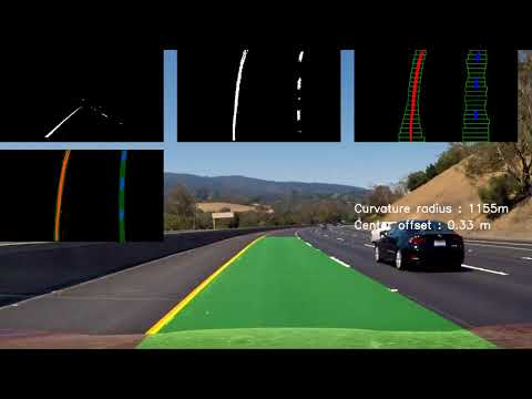
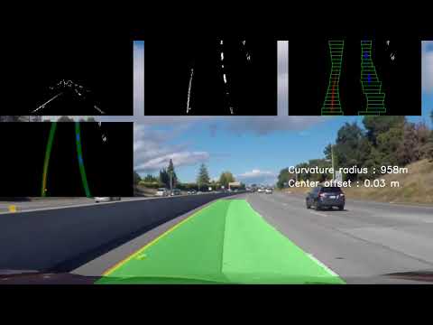
The fit from the rectified image has been warped back onto the original image and plotted to identify the lane boundaries. This demonstrate that the lane boundaries were correctly identified. An example image with lanes, curvature, and position from center is included.
- Example image of result


Here is a link to my final video output. The pipeline perform reasonably well on the entire project video
| Project Video | Challenge Video | Custom Video |
|---|---|---|
 |
 |
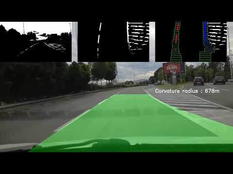 |
Briefly discussion about problems / issues I faced in my implementation of this project. Where will my pipeline likely fail? What could we do to make it more robust in the future?
The biggest problem of this pipeline is that it's hard for us to create composition of thresholds on color spaces or applying filters that will work fine on all road conditions, lights, shadows, noise. This pipeline may not work if we have different shade, or lighting condition around the road, and the thresholded image may not capture always the lane lanes and the information that we really need to extract. I solved the problem partially, if we don't get the lane lines, I switch the lane lines drawing in blind mode, and we draw the lane lines computed before, till we get enough data to represent the lines. But this is not ideal solution, and we need more powerful algorithm that can compose set of filters that can learn and construct the output in more consistent way. Because of that, I think that we cannot completely solve the problem with computer vision, we need machine learning algorithm that can learn how to annotate the road lane lines. We can use CNN architecture and we can use this algorithm to label some vides which can be used as train input/putput