This repository contains a firmware implementation of a composite USB device which exposes the following functionality:
- USB to UART conversion (fixed at a baudrate of 9600)
- USB HID gamepad/joystick interface via SPI
- 5 general purpose outputs, controlled over the SPI interface
It is designed to be used with the seeeduino xiao (ATSAMD21G18A). When flashed with the correct firmware, this will be hereafter referred to as a turtleboard.
Important notes:
- The seeeduino xiao supports 0V to 3.3V digital signals. Connecting signals outside this range will likely cause permanent damage to the device.
- For simplicity, the USB to UART baudrate is fixed at 9600. The device will ignore requests from the PC to change this.
- Download the firmware file
playful-turtle-xiao.uf2from the releases section of this repository. - Connect your seeeduino xiao to your computer with a USB C cable.
- Force your device into bootloader mode. To do this, you need to take a wire and connect the RST and GND pads together twice in quick succession. These two pads are located next to the USB connector on the board. See the animation at the end of this list for an example.
- A new USB storage device will appear connected to your computer (likely called "ARDUINO" or something similar)
- Copy and paste the
playful-turtle-xiao.uf2file onto the new storage device - The device will reflash its own firmware and then disconnect the storage device. You're now ready to go!
- (Your device may need a power cycle to start correctly the first time; just unplug and replug the USB cable.)
To use the USB to UART converter, simply connect the device to a free USB port on your computer. Drivers should be automatically installed on all platforms that need them. The device will appear in your operating system as a serial port.
The device supports 16 buttons, 2 joystick axes, 3 rotation axes and 4 direction pad buttons. Much like the USB to UART interface, drivers should be automatically installed on all platforms that need them.
The gamepad data can be sent using the SPI interface on the turtleboard; it behaves as a receive-only SPI slave (so there is no need to connect MISO as it is unused). The interface uses Motorola SPI mode 0, meaning that the clock polarity is active low, and the phase polarity is first/rising edge. The maximum supported clock speed of the interface is 1MHz.
All SPI transactions are two bytes long. The first byte is a register address, and the second byte contains the gamepad data. A list of the possible registers is below.
| Register address | Name | Format | bit 7 | bit 6 | bit 5 | bit 4 | bit 3 | bit 2 | bit 1 | bit 0 |
|---|---|---|---|---|---|---|---|---|---|---|
| 0x00 | BUTTON0 | 1 bit per button, 8 buttons | button 8 | button 7 | button 6 | button 5 | button 4 | button 3 | button 2 | button 1 |
| 0x01 | BUTTON1 | 1 bit per button, 8 buttons | button 16 | button 15 | button 14 | button 13 | button 12 | button 11 | button 10 | button 9 |
| 0x02 | JOYSTICK_X | 8 bit, two's-comp (-127 to 127) | ||||||||
| 0x03 | JOYSTICK_Y | 8 bit, two's-comp (-127 to 127) | ||||||||
| 0x04 | ROT_X | 8 bit, two's-comp (-127 to 127) | ||||||||
| 0x05 | ROT_Y | 8 bit, two's-comp (-127 to 127) | ||||||||
| 0x06 | ROT_Z | 8 bit, two's-comp (-127 to 127) | ||||||||
| 0x07 | DPAD | 1 bit per button, 4 buttons | X | X | X | X | right | left | down | up |
| 0x08 | GPO | 1 bit per output, 5 outputs | X | X | X | OUT4 | OUT3 | OUT2 | OUT1 | OUT0 |
| 0xFF | SEND_REPORT | X | X | X | X | X | X | X | X |
X = don't care
SEND_REPORT is a special register which, when written to, indicates to the device that it should send new the updated data to the PC as soon as possible. Due to the way that USB works, this update does not happen immediately. The device is configured to send updates every 2ms (500Hz), but this may be much longer depending on the USB host controller and operating system that the device is connected to. Note that the device will not report the gamepad data over USB automatically, you need to write to the SEND_REPORT register every time you wish it to send updated data to the PC.
It is safe to continue to perform SPI transactions whether or not the device has sent the updated data to the PC; if transactions occur on the SPI interface while an update is pending, they will either be ignored or merged with the pending data (depending on the exact timing). However, you should wait at least 1ms after driving CS high before driving it low again to send new data. This delay may need to be longer depending on how many USB devices are communicating with the PC at once. Typical symptoms of this being too low are repeated pulsing or glitching of input messages on the PC.
In the table above, the GPO register allows you to control 5 general purpose outputs. Simply write a bit to 1 drive the corresponding pin high, or 0 to turn it off. Updates to the output pins are as soon as possible; you do not need to send the SEND_REPORT command to have them update.
There are four LEDs next to the USB connector.
- The green LED indicates that the board is powered on.
- The yellow LED blinks when SPI data has been received.
- The two blue LEDs correspond to UART TX and RX activity.
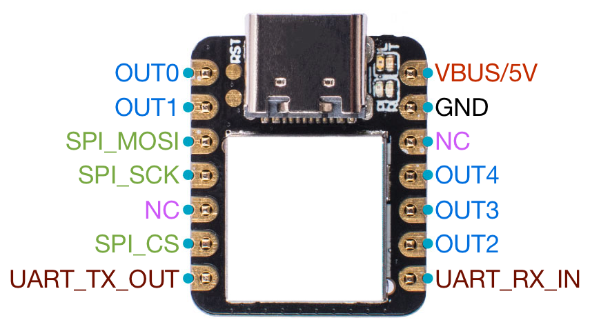
WARNING: Do not use the pinout information provided by seeedstudio.