Skip to content
New issue

Have a question about this project? Sign up for a free GitHub account to open an issue and contact its maintainers and the community.

By clicking “Sign up for GitHub”, you agree to our terms of service and privacy statement. We’ll occasionally send you account related emails.

Already on GitHub? Sign in to your account

RGBD sensor documentation is unclear/undefined #175

Closed
MarqRazz opened this issue Dec 12, 2021 · 10 comments · Fixed by gazebosim/sdformat#1109 or #259
Closed

RGBD sensor documentation is unclear/undefined #175

MarqRazz opened this issue Dec 12, 2021 · 10 comments · Fixed by gazebosim/sdformat#1109 or #259
Labels
bug Something isn't working help wanted Extra attention is needed

Comments

@MarqRazz
Copy link
Contributor

MarqRazz commented Dec 12, 2021

Environment

  • OS Version: Ubuntu 20.04
  • Binary build with some packages from source
    binary version: fortress
    source packages: ros_ign

Description

I am trying to setup an RGBD sensor for use with my robot (we are using ROS2 Rolling) and the documentation and example configuration of the RGBD camera are unclear how to properly setup the sensor.

I am having problems defining where the camera is located in simulation and the frame that the camera_info topic is returning.

Here is an example repo that a colleague and I are working on.
Here is an example gazebo.URDF file that I have used many times in ROS1 to emulate the Realsense D series camera.

issues:

  • the reference link I give does not work as expected. I would like to set the value to ${name}_depth_frame (or ${name}_link, they are in the same location) so that the camera is placed in the same location that Realsense publishes from.
  • The camera_info topic published to ROS comes in with the frame_id set as rgbd_camera/camera_bottom_screw_frame/rgbd_camera requiring a static frame publisher to view the images.
  • The documentation for the camera does not explain how its coordinate system is defined. If I view the images with the Camera widget in Rviz and add TF frames (for marker overlay) I can see that Z points out of the camera and X is to the right. Which means that my static transform is obviously not oriented correctly because it thinks the camera is pointed upwards. Is the expectation that this should be tied to an optical frame?
    image

Steps to reproduce

  1. clone this repo and follow the setup instructions
  2. launch the simulation with ros2 launch rgbd_camera_ignition rgbd_ignition.launch.py launch_rviz:=true

Output

Here is what the Ignition world looks like:
image

@MarqRazz MarqRazz added the bug Something isn't working label Dec 12, 2021
@iche033
Copy link
Contributor

iche033 commented Dec 14, 2021

Some quick answers. Ignition sensors produce data in the robot body frame: x forward, y left, z up. RViz expects camera image data to be in the optical frame: z forward, x right, y down.. We don't have an option to publish sensor data in optical frame right now in ign-sensors. That'll be nice to have. In one of our projects (ROS 1), we wrote an optical frame publisher that republishes data to optical frame through the static TF broadcaster:
https://github.com/osrf/subt/blob/master/subt_ros/src/OpticalFramePublisher.cc
https://github.com/osrf/subt/blob/master/subt_ros/launch/vehicle_topics.launch#L183-L191

@MarqRazz
Copy link
Contributor Author

Thanks for the pointers @iche033!

Ignition sensors produce data in the robot body frame: x forward, y left, z up. RViz expects camera image data to be in the optical frame: z forward, x right, y down.

This is true for ROS and real world cameras, why would Ignition make an emulated sensor that does not match a real world one (am I missing something here??)? I think all we need to do is change the name of the frame_id that Ignition is using in its camera_info topic(s) (which is currently some random string of rgbd_camera/camera_bottom_screw_frame/rgbd_camera in my case). You can see in Rviz that everything else is displayed properly except the marker overlay in the camera widget because it uses that frame_id in its calculations (I need to look at how the point cloud frame_id is defined but can fix this at the same time if I need to).

I would like to fix the plugin so you dont need additional static TF broadcasters to make it work. The optical frames are defined in the URDF and that should be enough (depth_optical_frame and color_optical_frame) if we pass the plugin the names of the frames.

If I were to add a variable that is read when loading the plugin to update name of the frame_id (FYI, I have not read through the code to see if that's the correct place to fix this) would you guys see any issues merging it? This is how you defined it in ROS1 and Gazebo classic and it worked great!

Thanks for your help and suggestions! I just want to make sure I'm on the right track before I make a PR.

@MarqRazz
Copy link
Contributor Author

MarqRazz commented Dec 18, 2021

So I have been attempting to fix this issues and have run into some problems. I am having the issue of Ignition collapsing all of my fixed frames (I have always disliked this feature!!) so I cant put the camera in the location that I want. As I said before my goal is to move the rendering and depth measurement to the frame camera_link which is the same location the Realsense uses. When I add the gazebo tag preserveFixedJoint for the joint camera_link_joint (which is between camera_bottom_screw_frame and camera_link) I get errors when launching ignition stating the following and my camera fails to spawn.

[ign gazebo-4] [Err] [UserCommands.cc:975] Error Code 16: Msg: A model must have at least one link.
[ign gazebo-4] [Err] [UserCommands.cc:975] Error Code 16: Msg: A model must have at least one link.
[ign gazebo-4] [Err] [UserCommands.cc:975] Error Code 24: Msg: FrameAttachedToGraph error: scope context name[] does not match __model__ or world.

You can see a few lines above I have also added preserveFixedJoint for the camera_joint which is between world and camera_bottom_screw_frame and that does not cause any issues.

When I inspect the frames in Gazebo I notice a few weird things.

  • There is a frame drawn on the face of the camera (camera_bottom_screw_frame is the little red and green arrows on the bottom of the camera). What frame could this be, I cant find any hard coded links in CameraSensor.cc or RgbdCameraSensor.cc?
    image

  • How can I verify where Ignition is rendering the camera images and measuring depth? In Gazebo classic you could get it to draw the camera frustum. Has this feature been ported to Ignition? Any help enabling this would be greatly appreciated!
    image

  • Why is the grid drawn above the ground plane? You can see that the wold frame is drawn below the grid in the following image. Are there other offsets that I am not accounting for?
    image

On the plus side I have figure out how to set the frame_id's for camera_info and point cloud so they are received by Rviz and rendered in the correct way! There was even a note in CameraSensor.cc that this needed to be done 😄. I will open up a PR as soon as I get the frame names read from the URDF/SDF. You can see in the GIF below that the point cloud is properly aligned with the RGB data when overlayed using the camera widget.
ignition_rgbd_camera

@MarqRazz
Copy link
Contributor Author

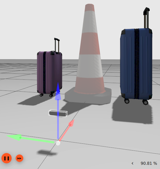
So I just though of another way that I can test where the camera is located and Ignition appears to be respecting where I place the sensor in the world (let me know if you see holes in this logic).

In my test I applied an additional offset of Y=0.1 and Z=0.1 between the frames camera_bottom_screw_frame and camera_link. You can see in the images below that the offset was applied in Ignition (the floating frame at the bottom of the image is camera_bottom_screw_frame).
image

And in Rviz you can see that the ground plane of the point cloud is aligned with the world frame (meaning my Z offset was properly applied) and that the construction cone is also offset to the right in the RGB image (which matches because I moved the camera to the left 0.1m).
image

@iche033
Copy link
Contributor

iche033 commented Dec 22, 2021

I get errors when launching ignition stating the following and my camera fails to spawn.

hmm the errors look like during the urdf -> sdf conversion process, a model with empty content is spawned. Not sure.

There is a frame drawn on the face of the camera (camera_bottom_screw_frame is the little red and green arrows on the bottom of the camera). What frame could this be, I cant find any hard coded links in CameraSensor.cc or RgbdCameraSensor.cc?

Could that be the camera_link itself? That's the only other link I see in the xacro file and its visual has some pose offset.

How can I verify where Ignition is rendering the camera images and measuring depth? In Gazebo classic you could get it to draw the camera frustum. Has this feature been ported to Ignition? Any help enabling this would be greatly appreciated!

the feature has not been implemented yet. I usually just create a small box visual at the origin of the camera help visualize where it is.

Why is the grid drawn above the ground plane? You can see that the wold frame is drawn below the grid in the following image. Are there other offsets that I am not accounting for?

The grid has a small pose offset so it gets rendered above the ground plane. I believe there is also an offset in gazebo classic. Here's the pose offset of the grid in Ignition: https://github.com/ignitionrobotics/ign-gazebo/blob/ign-gazebo6/src/rendering/RenderUtil.cc#L2542

On the plus side I have figure out how to set the frame_id's for camera_info and point cloud so they are received by Rviz and rendered in the correct way!

nice :)

@MarqRazz
Copy link
Contributor Author

So I made a PR against sdfFormat but somehow after getting that ready I have noticed there is now an offset in the point cloud data of 10mm in the Z (I have to manually add an offset to my URDF to remove it). I think when I was originally testing this I had sdf9 installed from binary but after building from source and updating to sdf12 the offset is present. I have not tired to roll back but if you guys have any ideas I would really appreciate the help tracking this offset down. Thanks!

If you look at the gif I posed above with the aligned clouds you can see that the point cloud is coincident with the grid and you can see half of the x-axis on the world joint because it intersects the cloud.

This is what the cloud looks like with the new offset.
image
image

@chapulina chapulina added the help wanted Extra attention is needed label Jan 25, 2022
@benediktkreis
Copy link

If I were to add a variable that is read when loading the plugin to update name of the frame_id (FYI, I have not read through the code to see if that's the correct place to fix this) would you guys see any issues merging it? This is how you defined it in ROS1 and Gazebo classic and it worked great!

Is it already possible to set the frame_id manually when using the ignition-gazebo-sensors-system plugin as it used to be in ROS1 and Gazebo classic? I would expect to be able to define the frame_id in a tag when declaring the camera sensor. That would look something like:

<sensor name="rgbd_camera_name" type="rgbd_camera">
  <origin rpy="0 0 0" xyz="0 0 0"/>"/>
  <camera>
    <horizontal_fov>1.5708</horizontal_fov>
    <image>
      <width>640</width>
      <height>360</height>
    </image>
    <clip>
      <near>0.1</near>
      <far>100</far>
    </clip>
  </camera>
  <always_on>1</always_on>
  <update_rate>30</update_rate>
  <visualize>true</visualize>
  <topic>rgbd_camera_topic</topic>
  <enable_metrics>true</enable_metrics>
  <frame_id>camera_link</frame_id>"/>
</sensor>

@iche033
Copy link
Contributor

iche033 commented Mar 17, 2022

that was added in #195. It reads the frame id by parsing an ignition-specific param, <ignition_frame_id> inside <sensor>. It's currently only available from source. A release with this change has not been made yet.

@benediktkreis
Copy link

@iche033 I've tested it and it works well for ignition.msgs.Image (image and depth image), but not for ignition.msgs.PointCloudPacked. The point cloud message doesn't use the frame_id specified in <ignition_frame_id>. The reason is that the frame_id isn't adjusted where the point message is defined (see e.g. #195 DepthCameraSensor.cc line 428)

Are you going to change the point cloud message code as you did for the image message any time soon (see e.g. #195 DepthCameraSensor.cc line 546)?

@benediktkreis
Copy link

Is there a possibility now to change the frame_id for the point cloud message with the <ignition_frame_id> tag or is there another tag for that?

Sign up for free to join this conversation on GitHub. Already have an account? Sign in to comment
Labels
bug Something isn't working help wanted Extra attention is needed
Projects
None yet
4 participants