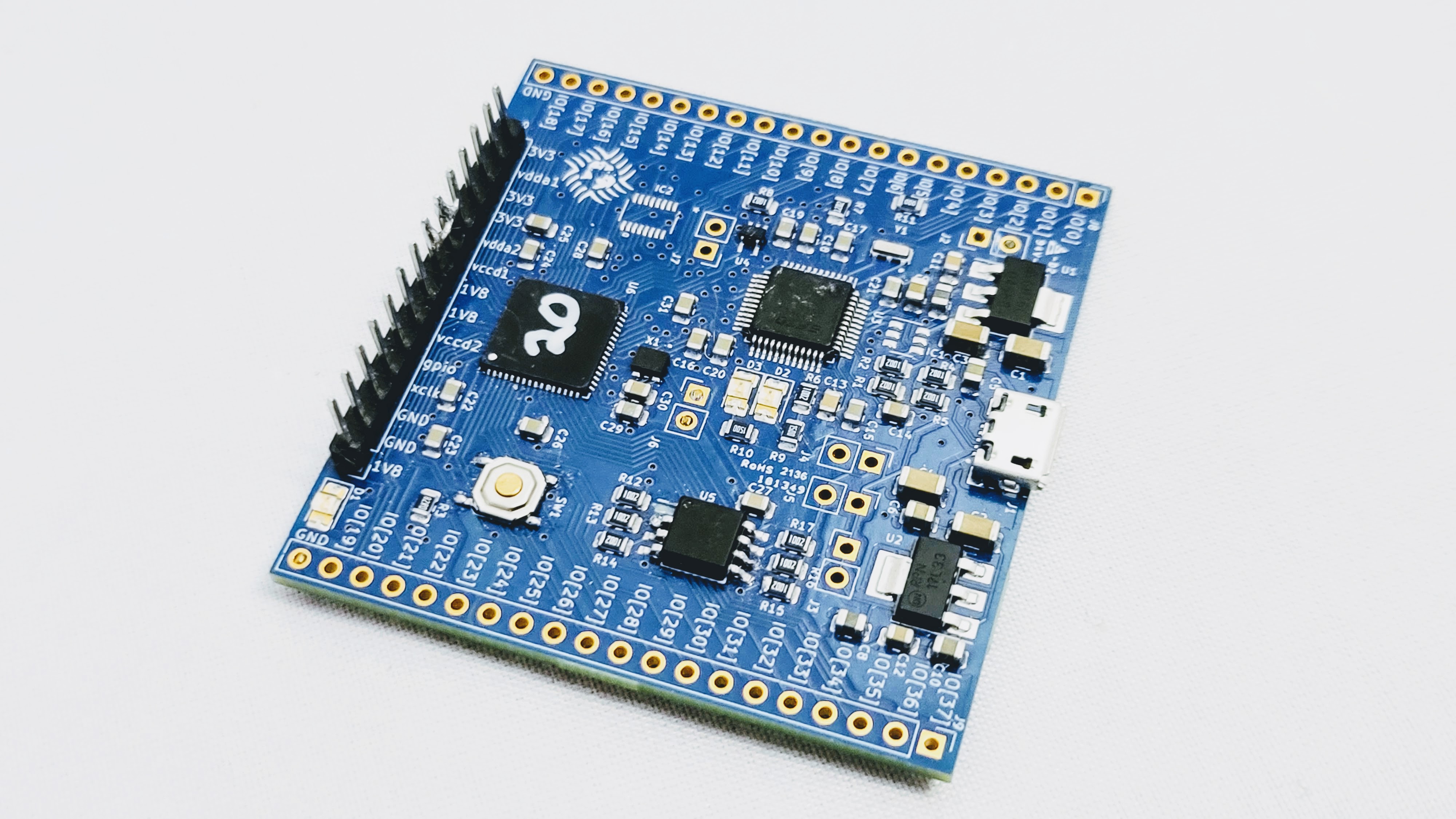
CLEAR is an Open Source FPGA ASIC delivered to you on its development board and its open source software development tools and all the ASIC design tools used to create it. That's for you to create your own - yes that's right - ASIC.
CLEAR is utilizing Caravel - the open source ASIC platform provided as a base System on Chip (SoC) provided by Efabless' chipIgnite offering.
- CNX Software - CLEAR is an open-source FPGA ASIC provided by Efabless’ chipIgnite
- hackster.io - Efabless' CLEAR Is a Fully Open Source ASIC with Embedded FPGA and RISC-V Core, Now on GroupGets
- 100% Open Source FPGA ASIC
- A small but not-so-little 8x8 (64) CLB eFPGA
- CPU Subsystem
- VexRISCV-based CPU
- 1.5 kilobytes of on-chip RAM (DFFRAM)
- Executes directly from external QSPI flash
- Peripherals
- SPI master
- UART
- 38 software configurable GPIO
- Counter/Timers
- Logic Analyzer
- Additional features
- Programmable internal clock frequency
CLEAR - Block Diagram
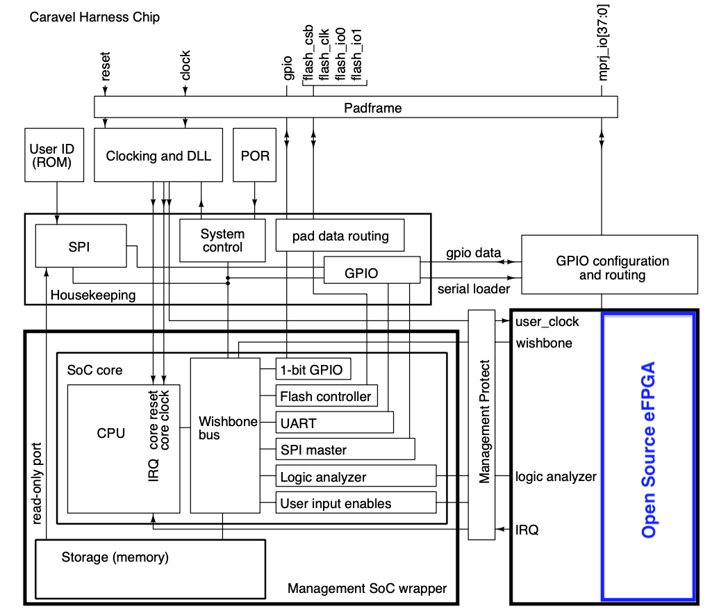
The layout is an 8x8 FPGA fabric generated using OpenFPGA and hardened using OpenLane.
Below is a detailed mapping of the I/O connections between Caravel and the user project, indicating the functionality and corresponding pins for each connection.
| IOs | Clear |
|---|---|
| mprj_io[0] | FPGA IO[46] |
| mprj_io[1] | HK SDO - FPGA isol_n |
| mprj_io[2] | HK SDI - FPGA IO[45] |
| mprj_io[3] | HK CSB - FPGA IO[44] |
| mprj_io[4] | HK SCK - FPGA IO[43] |
| mprj_io[5] | UART RX - FPGA IO[42] |
| mprj_io[6] | UART TX - FPGA IO[41] |
| mprj_io[7] | irq - FPGA IO[40] |
| mprj_io[8] | FPGA IO[39] |
| mprj_io[9] | FPGA reset |
| mprj_io[10] | FPGA test_enable |
| mprj_io[11] | FPGA IO[38] |
| mprj_io[12] | FPGA IO[37] |
| mprj_io[13] | FPGA IO[36] |
| mprj_io[14] | FPGA sc_tail |
| mprj_io[15] | FPGA IO[19] |
| mprj_io[16] | FPGA IO[18] |
| mprj_io[17] | FPGA IO[17] |
| mprj_io[18] | FPGA IO[16] |
| mprj_io[19] | FPGA IO[15] |
| mprj_io[20] | FPGA IO[14] |
| mprj_io[21] | FPGA IO[13] |
| mprj_io[22] | FPGA sc_head |
| mprj_io[23] | FPGA ccff_tail |
| mprj_io[24] | FPGA IO[127] |
| mprj_io[25] | FPGA IO[126] |
| mprj_io[26] | FPGA IO[125] |
| mprj_io[27] | FPGA IO[124] |
| mprj_io[28] | FPGA IO[123] |
| mprj_io[29] | FPGA prog_reset |
| mprj_io[30] | FPGA IO[122] |
| mprj_io[31] | FPGA IO[121] |
| mprj_io[32] | FPGA IO[120] |
| mprj_io[33] | FPGA IO[119] |
| mprj_io[34] | FPGA ccff_head |
| mprj_io[35] | FPGA clk_sel |
| mprj_io[36] | FPGA clk |
| mprj_io[37] | FPGA prog_clk |
RiscV is connected to FPGA IOs through logic analyzers, and that can be used to establish communication between the FPGA and RiscV
| FPGA IOs | Logic Analyzers |
|---|---|
| gfpga_pad_io_soc_in[47] | la_data_out[127] |
| gfpga_pad_io_soc_in[48] | la_data_out[126] |
| gfpga_pad_io_soc_in[49] | la_data_out[125] |
| ... | ... |
| gfpga_pad_io_soc_in[117] | la_data_out[57] |
| gfpga_pad_io_soc_in[118] | la_data_out[56] |
For a simple example to show how RiscV can communicate with the FPGA through Logic Analyzers can be found here
-
Clone this repo
git clone https://github.com/efabless/OpenFPGA_bitstream_generation.git -
Switch to SOFA branch
cd OpenFPGA_bitstream_generation git checkout SOFA -
Install dependencies
pip install -r requirements.txt -
Place the rtl design inside this directory
OpenFPGA/openfpga_flow/benchmarks/micro_benchmarkwhere also you can find other example designs -
Create a .pcf file for the design and place in this directory
OpenFPGA/openfpga_flow/tasks/SOFA_tasks/pcf_files. This is an example of a pcf file for ALU_4bits:
set_io operand_A[0] gfpga_pad_io_soc_in[46]
set_io operand_A[1] gfpga_pad_io_soc_in[45]
set_io operand_A[2] gfpga_pad_io_soc_in[44]
set_io operand_A[3] gfpga_pad_io_soc_in[43]

set_io operand_B[0] gfpga_pad_io_soc_in[42]
set_io operand_B[1] gfpga_pad_io_soc_in[41]
set_io operand_B[2] gfpga_pad_io_soc_in[40]
set_io operand_B[3] gfpga_pad_io_soc_in[39]

set_io operation[0] gfpga_pad_io_soc_in[37]
set_io operation[1] gfpga_pad_io_soc_in[36]

set_io result[0] gfpga_pad_io_soc_out[127]
set_io result[1] gfpga_pad_io_soc_out[125]
set_io result[2] gfpga_pad_io_soc_out[123]
set_io result[3] gfpga_pad_io_soc_out[122]
Important Notes:
- Change
operand_A,operand_B,operation, andresultto the ports of your rtl design. - If you didn't create a pcf file, the design ports to be assigned to random FPGA ios.
- OpenFPGA can detect the clk port in the design and connect it to the FPGA clk automatically.
-
You should change some variables in the
task.conffile you can find inside this directoryOpenFPGA/openfpga_flow/tasks/SOFA_tasks/config. This file points to all the files we will need like the openFPGA command files , the FPGA architecture xml files, the design to be implemented on the fabric , as well as the pin constraints file of the design. Make sure to change the following intask.confaccording to the design:- In
[OpenFPGA_SHELL], changeopenfpga_pcfvariable to point to pcf file of the design - In
[OpenFPGA_SHELL], changeopenfpga_vpr_fix_pins_filevariable to the name and path of the .place file which will be generated - In
[BENCHMARKS], changebench0to point to the path of the verilog file/s of the design you want to implement - In
[SYNTHESIS_PARAM]changebench0_topto be the name of the top module of the design
- In
-
After placing the rtl and pcf and editing task.conf, you should just run
python3 openfpga_flow/scripts/run_fpga_task.py SOFA_tasks
- You will find all the files related to the run in a folder inside the task in the directory
OpenFPGA/openfpga_flow/tasks/SOFA_tasks/run_xx. It will contain all results like the fabric src files, the synthesized design, a testbech , the bitstream, and the io_mapping.
| Design | # CLBs | CLB Util | # I/O Blocks | # FFs | # LUT |
|---|---|---|---|---|---|
| fpga_ram8x20 | 41 | 64% | 23 | 168 | 316 |
| fpga_ram8x16 | 33 | 51.5% | 22 | 136 | 252 |
| fpga_mac_6x6 | 14 | 21.9% | 26 | 13 | 108 |
| fpga_LFSR | 8 | 12.5% | 25 | 48 | 60 |
| fpga_seq_mul | 8 | 12.5% | 34 | 28 | 65 |
| fpga_mac | 7 | 11% | 18 | 9 | 47 |
| seconds_decoder | 7 | 11% | 9 | 35 | 50 |
| fpga_ring16 | 7 | 11% | 17 | 40 | 52 |
| fpga_pwm8 | 3 | 4.7% | 18 | 9 | 22 |
| ALU_4bits | 2 | 3.13% | 14 | 0 | 12 |
-
Clock Source Selection: The FPGA can utilize two external clock sources:
- GPIO 36
- Caravel clock
Selection is controlled via GPIO 35. To assign the clock:
assign clk = clk_sel ? wb_clk_i : io_in[36];
-
Initialization and Configuration:
- Isolate the FPGA I/Os by setting
isol_nto 0. - Reset the FPGA by asserting
prog_reset. - Begin programming by providing the
prog_clkand the bitstream viaccff_head. - Once programming is complete, the FPGA I/Os can be utilized by asserting
io_isol_n. - Reset the operational configuration by asserting
op_reset. - Provide the operational clock
op_clkand any necessary I/O inputs and outputs.
- Isolate the FPGA I/Os by setting
-
Important Notes:
- Ensure to configure Caravel GPIOs correctly.
- The sequence of isolation, reset, and clock selection is crucial for proper operation.
Here the bitstream is converted to a C header file and added as part of the firmware, so that the bitstream is stored in the flash memory, and the firmware uses it to configure the FPGA through the GPIOs.
In order to use this method you need to short some IOs on caravel
| FPGA prog IO | Shorted IO | Function |
|---|---|---|
| GPIO[1] | GPIO[17] | io_isol_n |
| GPIO[9] | GPIO[18] | op_rst |
| GPIO[29] | GPIO[19] | prog_rst |
| GPIO[34] | GPIO[20] | ccff_head |
| GPIO[35] | GPIO[21] | clk_sel |
| GPIO[37] | GPIO[24] | prog_clk |
In order to use this method you need to do a couple of extra steps:
- generate the header file from the bitstream, using this command from your test directory
make generate_header
- Include your header file in the C code for example:
#include <and_3.h>
- Configure the shorted IOs in your C code as follows:
configure_gpio(7, GPIO_MODE_MGMT_STD_OUTPUT); // connected to prog_clk
configure_gpio(8, GPIO_MODE_MGMT_STD_OUTPUT); // connected to prog_rst
configure_gpio(9, GPIO_MODE_MGMT_STD_OUTPUT); // connected to op_rst
configure_gpio(12, GPIO_MODE_MGMT_STD_OUTPUT); // connected to isol_n
configure_gpio(13, GPIO_MODE_MGMT_STD_OUTPUT); // connected to ccff_head
configure_gpio(14, GPIO_MODE_MGMT_STD_OUTPUT); // connected to clk_sel
- Add this function after configuring the IOs
process_bit_stream(and_3_size, and_3);
An example test for this method can be found here
- Go to the the test directory for example
cd firmware/and_gate_firmware
- Run the make file
make flash
Note
To flash correctly, you need to run firmware/util/ftdi_flash.py