A collection of simple and basic circuits.
WARNING!! This repo is a collection of note and tests, is not always trusted.
- Voltage Divider Circuit
- LED Indicator Circuit
- RC Circuits
- Coupling and Decoupling
- Power Circuit
- Switch Circuit
- Digital Logic Circuits
- H-Bridge Circuits
- Diode Bridge Circuit
- Pull-up/pull-down Resistor Circuits
- Debouncing Circuit
- Level up/down Circuit (Amplifier)
Rtot = 1 / (1/R1 + 1/R2 + 1/R3 ... + 1/Rn)
Rtot = R1 + R2 + R3 ... + Rn
I = V/R or V = RI or R = V/I

- R1 = 110ohm
- R2 = 330ohm
- R3 = 220ohm
- Vcc = 12V
The total resistance of the circuit is Rtot = R1 + R2-3 = 110 + 132 = 242ohm where R2-3 = 1 / (1/R1 + 1/R2) = 1 / (1/330 + 1/220) = 132ohm
The current on the circuit is I = V / Rtot = 12 / 242 = 0.05A = 50mA
The voltage between A and B is VA-B = R1 * I = 110 * 0.05 = 5.5V
The voltage between B and C is VB-C = R2-3 * I = 132 * 0.05 = 6.6V
So, V = VA-B + VB-C = 5.5 + 6.6 = 12.1V
The colored bands over the resistors indicate their resistance, using this table you can find the value:

Is the smallest circut used to power a LED (Light Emitting Diode)

The R1 resistor depends on the Vcc voltage and on the LED type. For e 3mm LED at 5 VDC, for example, this are the rounded values:
| Size | Color | Forward current | Foward voltage | Resistor |
|---|---|---|---|---|
| 3mm | Red | 20mA | 1.8 VDC | 160 ohm |
| 3mm | Green | 20mA | 2.2 VDC | 140 ohm |
| 3mm | Yellow | 20mA | 2.1 VDC | 145 ohm |
| 3mm | Blue | 20mA | 2.8 VDC | 110 ohm |
In general, the formul is:
R = (Vcc - VL) / IL
Q = CV o V = Q/C o C = Q/V
Ctot = C1 + C2 + C3 ... + Cn
Ctot = 1 / (1/C1 + 1/C2 + 1/C3 ... + 1/Cn)
Vi = Q/Ci

- C1 = 10nF
- C2 = 50nF
- C3 = 20nF
- Vcc = 12V
The total capacitance of the circuit is Ctot = 1 / (1/C1 + 1/C2-3) = 1 / (1/10 + 1/70) = 8.75nF where C2-3 = C1 + C2 = 50 + 20 = 70nF
The total electric charge is Qtot = Ctot * Vcc = 8.75*10-9 * 12 = 105nQ
The voltage between A and B is VA-B = Q / C1 = 105 / 10 = 10.5V
The voltage between B and C is VB-C = Q / C2-3 = 105 / 70 = 1.5V
So, V = VA-B + VB-C = 10.5 + 1.5 = 12.1V
This is a simple circuit with a capacitor:

When we push the button, the current flows in the circuit and the LED lights up; this current also flow in the capacitor and charge his plates. When we release the button, the current stop to flows from power supply but flows out of the capacitor, so the LED still lights until the capacitor will discharged.
The code over the capacitors indicate their capacitance, using this table you can find the value:
| 1st 2nd number | 3rd number | Multiply with |
|---|---|---|
| xx | 0 | 1 |
| xx | 1 | 10 |
| xx | 2 | 100 |
| xx | 3 | 1,000 |
| xx | 4 | 10,000 |
| xx | 5 | 100,000 |
| xx | 6 | 1,000,000 |
| xx | 7 | Not used |
| xx | 8 | 0.01 |
| xx | 9 | 0.1 |
| xRx | / | 0.1 |
In general, the first two digit are the value, the 3rd is the multiplier and the letter is for tollerance. The very small capacitors can have an R between the first and second digits, this means that there is a point (ex. 2R2 = 2.2pF).
In other case, the value wrote above capacitor is in micro-farad (es. .33) or with specified multiplier (es. 330n).
| Value | Type 1 | Type 2 | Type 3 |
|---|---|---|---|
| 100nF | 101 | 100n | .1 |
| 120nF | 124 | 120n | .12 |
| 150nF | 154 | 150n | .15 |
If there is a uppercase letter after the code, it represents the tollerance (ex. .33K):
| Letter | Tolerance |
|---|---|
| D | 0.5pF |
| F | 1% |
| G | 2% |
| H | 3% |
| J | 5% |
| K | 10% |
| M | 20% |
| P | +100% / -0% |
| Z | +80% / -20% |
If there is a number after the tollerance, it represents the voltage (ex. .33K63).
Normally, on the electrolytic capacitors, there are the capacitance and the max voltage wrote in the clear form.
Is possible to made a simple voltage divider using two resistance:

Vout = (R2 / (R1 + R2)) * Vin
With a voltage divider, a certain amount of current is wasted; with biggest resistors we get smallest consumption.
- R1 = 110ohm
- R2 = 330ohm
- Vcc = 12V
Vout = (R2 / (R1 + R2)) * Vin = (330 / (110 + 330)) * 12 = 9V
This is a example that allow you to indicate the locical value in a line.

LED1 indicate the 1 logic state, LED2 indicate the 0 logic state.
This is possible because a LED is a diode, so it allow the current flow only from positive to negative. When the line is at Vcc, LED1 allow current flow so it's on and LED2 is off. Vice versa, when the line is at GND, LED2 don't allow current flow so it's off and LED2 is on.
An RC circuit is made by a resistor and a capacitor.

This is the simplest RC circuit. When we push the button, the capacitor will charge.
When we release the button, the circuit is short-circuited and the capacitor will discharge.

The total charging/discharged times is T = R * C (ex. 4.5kΩ * 1000uF = 4,7s).
The RC circuits can be used to filter a signal in frequncy. The cutoff frequency can be determined by the time constant:
fc = 1 / (2πRC)
- C1 = 10nF
- R1 = 220ohm
The cutoff frequency is fc = 1 / (2πRC) = 1 / (2π * 1000 * 10*10-9) = 15.91kHz.

A low-pass filter is a filter that cut the frequencies higher than the cutoff frequency.

A high-pass filter is a filter that cut the frequencies lower than the cutoff frequency.
In electronic, the capacitors are very used for their property of blocking constant currents and let passing the variable currents.

A decoupling capacitor (also called bypass capacitor) is used for join two part of the circuit far and prevent variation of the voltage (nois). When there is an high peak of curren, the capacitor absorb it; vice-versa, when there is an low peak of curren, the capacitor release the electric charge. A decoupling capacitor is usually placed near of the IC's power pins.

A coupling capacitor (also called DC-blocking capacitor) is used for separate two part of circuit and prevent passing of DC current, so only the AC signal from the first circuit can pass through to the next.
The standard voltage regulator is a component that allow us to get a normalized current and voltage. Every voltage regulator have a specific max Vin level and in order to get clean power, the datasheets recommends to using a capacitor.

In this circuit I added a 12V diode in order to perform a simple reverse polarity and overvoltage protection.
A good utilities in the electronics experiments is the switch, that allow us to pilot a device.

The first version of switch is called low-side switch because the transistor are in the low side of the circuit. The second one is called high-side switch for the same reson.
The switch can be used for pilot higher voltage devices (according to the transistor specification) like a motor.
The transistor is a semiconductor device very used in eletronic. They have two base use case:
- interrupt a signal (switch)
- aplifing a signal
There are many transistor type that have different caratteristic:
- Bipolar junction transistor (BJT), most used in analog circuits because of their greater linearity and ease of manufacture
- Field-effect transistor (FET), most used in digital circuit
All the type can be P-channel (PNP) or N-channel (NPN).
Transistor have 3 pad called emitter (E), base (B) and collector (C).

On the NPN transistor (in the simbol arrow Not Point iN :-) ) the main current flows from C (+) to E (-) and the controlling current flows from B (+) to E (-).
Conversely, on the PNP transistor (in the simbol arrow Point In) the main current flows from E (-) to C (+) and the controlling current flows from E (-) to B (+).
IE = IB + IC
Is good to remember that the real electron flow is opposit of theoretical current flow.
Another interesting use of the transistors is to do a digital logic operation.

The first schema represent a NOT gate, if A is at VCC the output is at GND and vice-versa.
The second schema represent a 2-input AND gate, if A and B are at VCC the output is at VCC, GND otherwise.
The last one represent a 2-input OR gate, if A or B are at VCC the output is at VCC, GND otherwise.
In orther to pilot a DC motor an H-bridge is required.

The H-Bridge take his name from the form of his schema.
If INA and and INB are both at the same voltage, OUTA and OUTB will be at the same voltage, so the motor won’t be able to spin.
| Input A | Input B | Output A | Output B | Motor Direction |
|---|---|---|---|---|
| 0 | 0 | 1 | 1 | Stopped (braking) |
| 0 | 1 | 1 | 0 | Clockwise |
| 1 | 0 | 0 | 1 | Counter-clockwise |
| 1 | 1 | 0 | 0 | Stopped (braking) |
A well designed H-bridge must to be more complex.
Usually, a IC (es. L293) is used instead a homemade H-bridge.
A Diode Bridge is a circuit that provides the same polarity of output for either polarity of input and it's made by 4 diode.

If the V1 supply is positive, current flows through D3 to Vcc and flows to V2 through D2. Vice versa, if the V1 supply is negative, current flows through D4 to Vcc and flows to V1 through D1.
The Diode Bridge is good to correct Power Circuit inverted polarity, but it allow us to convert an AC input into a DC output, for this porpuse, the addition of a capacitor is recomanded in order to prevent an output of pulsed DC.

A pull-up resistor (or pull-down) is a circuit that prevent the unknow state on input pin of a MCU when nothing is connected.
Pull-ups and pull-downs are often used with buttons and switches.

In the pull-up circuit, when the button isn't pressed, a small ammount of current flows through the resistor to the MCU's input pin, so the MCU read an HIGH state. When the button is pressed, the current flows through the resistor (and through MCU's pin) to GND so the MCU read a LOW state.
Pull-up and pull-down circuits are equals but pull-up connect pin to Vcc and pull-down connect pin to GND.
If there isn't a resistor when we press the button, circuit will put in "short".
The value of the resistor is usually 10Kohm but it depends to the MCU input pin impedance. For example, the Arduino Uno's input pin inpedance is 100Mohm, so:
I = V / Rtot = 5 / (10*10^3) = 0.0005A = 0.5mA
The current over the circuit is inversely proportional to the R1 value, so if we increase R1 the current consumpted in the quiet state will decrese, but R1 and R2 generate also a voltage divider:
Vout = (R2 / (R1 + R2)) * Vin = (100*10^6 / (10*10^3 + 100*10^6)) * 5 = 4,99V
The Arduino Uno's brown-out detection is 2.7V, so if we use a a resistor of 100Mohm for R1, the logic level on Arduino Uno's input pin will be always LOW.
Vout = (R2 / (R1 + R2)) * Vin = (100*10^6 / (100*10^6 + 100*10^6)) * 5 = 2,5V
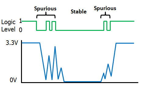
A debouncing circuit is a simple circuit used for connect a push button to a MCU.

Apart from the pull-up resistor, there are also a decoupling capacitor that prevent the signal bouncing when we press the button.
Without this capacitor, when we press the button and read the value on the input pin of the MCU, we will read an unstable level.
Is also possible preventing bouncing by software using debounce delay.

## BS-06 Bluetooth Module
The BS-06 is a slave only module, so you can send command from other device to him but not vice versa.
The BS-06 work at 3.3V but I used a module with a pass-through adapter and a voltage regulator, so i must use a 5V power supply.
For a test, we can connect a serial adapter to the module and then we can connect to the device with command:
sudo python -m serial.tools.miniterm /dev/tty.wchusbserial1410 9600 --eol LF
After this, we can send an AT command by copying and pasting on terminal.
| COMMAND | RESPONSE | COMMENT |
|---|---|---|
| AT | OK | Used to verify communication |
| AT+VERSION | OKlinvorV1.8 | The firmware version (version might depend on firmware) |
| AT+NAMEaaa | OKsetname | Sets the module name to “aaa” |
| AT+PIN1111 | OKsetPIN | Sets the module PIN to 1111 |
| AT+BAUD1 | OK1200 | Sets the baud rate to 1200 |
| AT+BAUD2 | OK2400 | Sets the baud rate to 2400 |
| AT+BAUD3 | OK4800 | Sets the baud rate to 4800 |
| AT+BAUD4 | OK9600 | Sets the baud rate to 9600 |
| AT+BAUD5 | OK19200 | Sets the baud rate to 19200 |
| AT+BAUD6 | OK38400 | Sets the baud rate to 38400 |
| AT+BAUD7 | OK57600 | Sets the baud rate to 57600 |
| AT+BAUD8 | OK115200 | Sets the baud rate to 115200 |
| AT+BAUD9 | OK230400 | Sets the baud rate to 230400 |
| AT+BAUDA | OK460800 | Sets the baud rate to 460800 |
| AT+BAUDB | OK921600 | Sets the baud rate to 921600 |
| AT+BAUDC | OK1382400 | Sets the baud rate to 1382400 |
If you send an AT message, the module response with an OK message.
For a complete test, I used a bluetooth terminal app installed on my Android device, I connected the BS-06 to the phone and I sent a message to the module.
If you read your message on the computer terminal all works fine.
| Name | Color | Note |
|---|---|---|
| GND | black / blue | |
| Vcc | red | |
| RX | orange | |
| TX | yellow | |
| RESET | green | |
| MISO | white | |
| MOSI | gray / orange | orange deprecated |
| SCK | brown | |
| RESET | green / gray | gray deprecated |