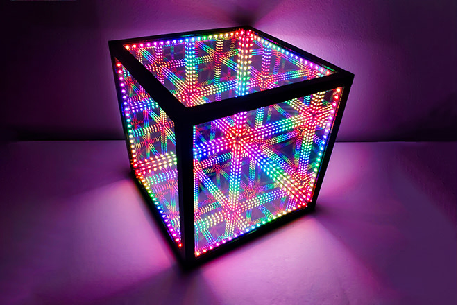
This project on indigogo striked my eye https://www.indiegogo.com/projects/the-hypercube#/ .
The problem was, that i wanted to control it over my HomeAssistant instance.
So i set out to build my own version, to which i could add my own features.
- WS2812B led light strip, 60led/m, ~1.2-1.5m
- 6 semi-transparent mirror panes (or glass+semi-transparent mirror foil),20*20cm
- esp32
- 1x500 ohm resistor
- wire, preferably red black and other color for data
- breadboard
- 5V power supply
- 3d-printer
- soldering iron
- hot glue gun
The complete Design will look like this:
Each side beam will fit two glass panes, the cross-section sketch looks like this:
Resulting in this beam:
The beams are connected in corners, these corners should connect the beams, align seemlessly and fill the corners on the inside of the cube.
My design with integrated support(my slicer didnt construct one so i hand modeled one) looks like this:
One Test print of the shorter versions of the beams:


Since you cannot find an euler path over the edges of a cube, it is impossible to directly connect all edges of the cube without taking edges twice, so we have to lay cables inside of beams in order to get power and data to all leds.
I arranged the data flow in this way:
Red are the led strips, green is a cable going back inside the beam. Each edge is numbered in order in accordance to wiring

- Cut the Led strips in parts of 12 leds each
- glue the strips central on each beam
- make a hole in one corner for the wires to enter the system
- assemble 1,2,3,4,5,6
- insert bottom mirror
- add 7 and 8
- build 9,10,11,12 seperatly with mirror
- insert side mirrors
- bring bottom and top together, for this i used longer cables which make a loop in the beam for easy assembly and more leeway. like this:

The purpose of the microcontroller is to control the colors of the leds. The complete system is powered by a power supply delivering 5V. Since the microcontroller and the leds have the same voltage, we dont need a step down or step up converer.
The entire diagram looks like this:

The general structure of the code will look as follows:
- setup network connection
- initialise led library
- subscribe to MQTT
- loop:
- calculate new color for leds
- handle mqtt messages
The main concern with calculating colors for the leds is, that they are addressable in a single dimension by the starting index of the led strip. Since the stip is cut at every corner of the cube, the numbering of the leds is not continuous. Se we need a way to color leds independently of their index.
My solution to this problem is to color leds based on their position in 3d
My algorithm is based on the euclidean distance of the location of a led to a reference Point

To calculate the positions, we need to know which sections of leds start in what corner of the cube, and in which direction they go. This is given in
rowDirections and rowBeginPositions as points with x,y,z components. We also need these distances:

#define startLedDistance 0.65/20
#define interLedDistance 1.7/20

void calculatePositions(){
 point rowDirections[12]={
   { 0, 0, 1 },
   { 0, 1, 0 },
   { 1, 0, 0 },
   { 0, 1, 0 },
   { 0, 0, -1},
   { 0, 1, 0 },
   { -1, 0, 0 },
   { 0, 1, 0 },
   { 1, 0, 0 },
   { 0, 0, 1 },
   { -1, 0, 0 },
   { 0, 0, -1 }
 };
 point rowBeginPositions[12]={
   { 0, 0, 0 },
   { 0, 0, 1 },
   { 0, 0, 1 },
   { 1, 0, 1 },
   { 1, 0, 1 },
   { 1, 0, 0 },
   { 1, 0, 0 },
   { 0, 0, 0 },
   { 0, 1, 0 },
   { 1, 1, 0 },
   { 1, 1, 1 },
   { 0, 1, 1 }
 };
 for(int i=0;i<12;i++){
   for(int j=0;j<NUM_LEDS/12;j++){
     ledPositions[i*12+j].x=rowBeginPositions[i].x+rowDirections[i].x*(startLedDistance+j*interLedDistance);
     ledPositions[i*12+j].y=rowBeginPositions[i].y+rowDirections[i].y*(startLedDistance+j*interLedDistance);
     ledPositions[i*12+j].z=rowBeginPositions[i].z+rowDirections[i].z*(startLedDistance+j*interLedDistance);
   }
 }
}
For the actual color calculation, we define a function that takes the index of the led. It calculates the distance from the reference Point to the led position, scales it through the max distance, which is defined as the distance of two opposing corners in the cube, or sqrt(3). After that is adds a offset based on the time, to create a smooth effect. This value is then used to access the color palette and assigned to the led.
void calculateColor(int number){
  point x= ledPositions[number];
  double distance = sqrt((x.x-reference.x)*(x.x-reference.x)+(x.y-reference.y)*(x.y-reference.y)+(x.z-reference.z)*(x.z-reference.z));
  uint8_t normalised = distance/distanceMax*255;
  uint8_t heatindex = sin8((millis()%5100)/20-normalised);
  leds[number] = ColorFromPalette( myPal, heatindex);
}
For a more diversified lighting effect, i simulate the reference point. It starts at a position and a direction inside the cube. It then bounces inside the cube, similar to the dvd screensaver icon. This process is straight forward.
void movePoint(float factor){
  reference.x+=moveDirection.x*factor;
  if(reference.x<0){
    moveDirection.x*=-1;
    reference.x*=-1;
  }
  if(reference.x>1){
    moveDirection.x*=-1;
    reference.x=2-reference.x;
  }
  reference.y+=moveDirection.y*factor;
  if(reference.y<0){
    moveDirection.y*=-1;
    reference.y*=-1;
  }
  if(reference.y>1){
    moveDirection.y*=-1;
    reference.y=2-reference.y;
  }
  reference.z+=moveDirection.z*factor;
  if(reference.z<0){
    moveDirection.z*=-1;
    reference.z*=-1;
  }
  if(reference.z>1){
    moveDirection.z*=-1;
    reference.z=2-reference.z;
  }
}
The process of calculating new colors should happen in a fixed cycle. This cycle is 60hz in my case. Too achieve this goal, i didnt want to use sleep, so employed a check at the beginning of each loop if deltaT is big enough to start the new cycle. If not count up a counter until that time is reached. The size of the counter represents the remaining calculation time i could use each frame. So if the counter is 5000 i can implement new features in the color calculation process, which should decrease this number. Once this number reaches 0 i have too much code running each cycle, such that i cannot reach my target update rate, so i should either optimise the calculation code or decrease the update rate.
To track irregularities in execution i print the timeouts to serial, if it deviates by 10% to the last timeouts. Such a deviation can result in extra code execution, like the handling of a MQTT message.
After this update rate control we can
- move the referncene point
- calculate the colors of the leds
- let FastLED update the leds over SPI
- handle MQTT messages
EspMQTTClient client;
unsigned long lastTick;
float fpsDeltaT = 1.0/60.0*1000;

void loop() {
  //fps control
  int timeouts=0;
  while(millis()-lastTick<fps){timeouts++;}
  if(timeouts==0)
   Serial.printf("%fCant keep up, deltaT was %f\n",fps,millis()-lastTick);
  else if(((float)(abs(timeouts-averageTimeouts)))/timeouts>0.1){
    averageTimeouts=timeouts;
    Serial.printf("Next Frame Timeouts is deviating to %d\n",averageTimeouts);
  }
  lastTick=millis();
  ...
  movePoint(speed*fps);
  FastLED.clear();
  for(int i=0;i<NUM_LEDS;i++){
    calculateColor(i);
  }
  FastLED.show();

  client.loop();
}
The HomeAssistant(HA) MQTT Light protokoll is defined here: https://www.home-assistant.io/integrations/light.mqtt/. After connection with the MQTT Broker the cube has to send an available message on startup as well as subribe to the commands which HA sends to the cube.
  void onConnectionEstablished()
{
  client.subscribe(CHANNEL_MQTT_LIGHT_COMMANDS, &handleMessage);
  client.publish(CHANNEL_AVAILABLITY, "online");
}
To handle messages sent by HA, a handler subscribes to a defined topic. This function decodes the received json message and adjusts the state accordingly. For color changes we need to create a now color palette from the given rgb value. After this it needs to publish the state change so HA knows it has processed the command.
void handleMessage(const String & payload){
 Serial.println("incoming: " + payload);
 DynamicJsonDocument json(1024);
 deserializeJson(json, payload);
 String deviceOn = json["state"];
 int rec_brightness = json["brightness"];
 long rec_spectrumRgb = json["spectrumRgb"];
 long my_spectrumRgb;

 if (deviceOn == "ON")
 {
   Serial.println("ON");
   state="ON";
   FastLED.setBrightness(brightness);
 }

 if (deviceOn == "OFF")
 {
   Serial.println("OFF");
   state="OFF";
   FastLED.setBrightness(0);
 }

 if (!json["brightness"].isNull())
 {
   FastLED.setBrightness(rec_brightness);
   brightness=rec_brightness;
   Serial.println("brightness");
   Serial.println(rec_brightness);
 }
 if (!json["color"].isNull())
 {
   changeColorPalette(json["color"]["r"],json["color"]["g"],json["color"]["b"]);
 }
 publishStateChange();
}
For adding MQTT Lights to your existing HA instance see https://www.home-assistant.io/integrations/light.mqtt/.
The control Panel will then look like this
 .
.

It also has different lighting modes, but they dont work on the same mechanism as the cube with calculating distances.
The important thing is, that it has a button which can make my cube light up, and i can make her heart light up.
I'm not gonna go into detail on how i built her device in this repository, but this may follow one day. I also know that my implementation of the light up mechanism in the version of the cube is not the best, but i have not found the time and muse since. It is eg not possible for the cube to receive the light up message while it is on.
If you feel like helping out, feel free to create a PR.
The implementation of the light up mechanism is quite simple, the communication is also going over MQTT. The script will listen on the topic defined in CHANNEL_HEARTBEAT_RX and then change state to "heart".
In the heart state the leds will slowly light up and then go out again, once this is over the state is set back to off mode.
The light up works by defining a time in messageLength and a hue value in heartHue.
The light will then go up and down in the form of a sinus wave.
The code looks like this:
if(state=="heart"){
    if(millis()-messageStartMillis>messageLength){
      state="OFF";
      FastLED.setBrightness(0);
    }
    float percentDone= ((float)(millis()-messageStartMillis))/((float)(messageLength));
    percentDone*=2;
    if(percentDone>1){
      percentDone=-percentDone+2;
    }
    uint8_t unscaled =(uint8_t)(percentDone*255);
    uint8_t scaled = scale8( unscaled, 200);
    CHSV color= CHSV(heartHue,200,scaled);
    FastLED.clear();
    for(int i=0;i<NUM_LEDS;i++){
      leds[i]=color;
    }
    FastLED.show();

  }